Few weeks ago a friend of mine gave me an AVR64DU32 Curiosity Board (an evaluation/tinkering board with one of the new AVR Dx micros on it) to start poking around.
Here's how I set up a basic environment to work with my usual toolchain (avr-libc, avr-gcc and avrdude).
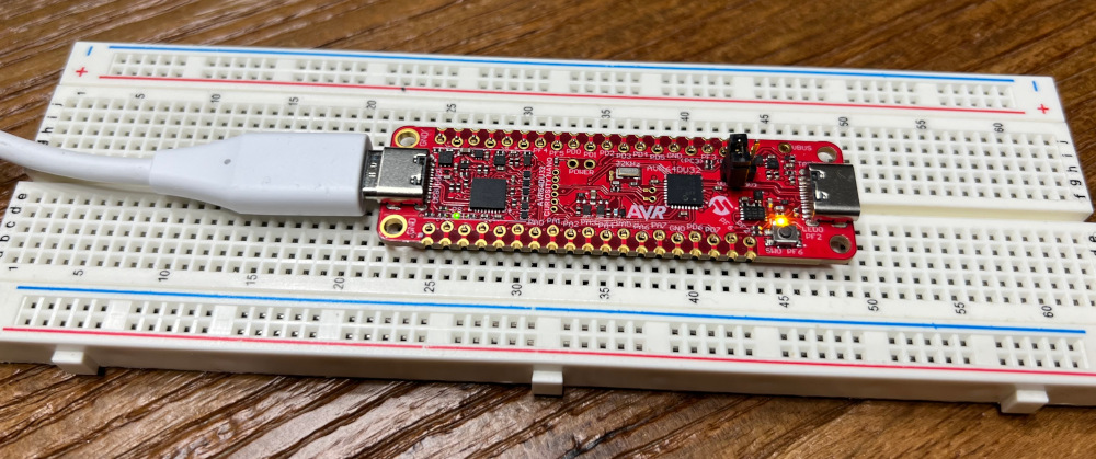
The board
This is the AVR64DU32 Curiosity Nano board. It uses an AVR64DU32 (64 KB memory, DU family - the one with USB capabilities, 32 pins) and can be programmed with just a USB-C cable.
Those new micros are programmed via UPDI instead of the "classic" ISP. Since this board has its own programmer I still need to dig more there, but found this repo with a collection of different programmers.
Setting up the environment
When working with Atmel stuff (on Linux, Debian or Debian-based machine) I usually need:
- binutils, targeted with avr when compiled
- avr-gcc (gcc targeted with avr)
- avr-libc
- avrdude
To make sure there's support for those Dx (the apt packages are kinda old) the newest versions of avr-libc and avrdude were used (and also the newest binutils and avr-gcc too).
Also, an old version of gcc installed via apt was used to compile everything (even the newest avr-gcc) and it worked flawlesly.
binutils
- Go to the website and download the latest version
- Decompress
./configure --target=avr
make
make install
Check there's some stuff in
/usr/local/bin/, such as
avr-ld
avr-gcc
- Go to the website and download the latest version
- Decompress
- Install
g++
via apt - In order to fix some dependencies when compiling, needed to execute the
./contrib/download_prerequisites
script to install additional dependencies (more about this) - Create a folder inside the main source folder and execute the
./configure
andmake
inside that folder. Doing the whole process in the main source folder will eventually fail (and it takes a while...) ./configure
make
make install
avr-libc
- Go to the website and download the latest version
- Decompress
./configure --build=
./config.guess
--host=avr
make
make install
Library will be installed on
/usr/local/avr/
Hello World
Now it's time to some blinking effects with the built-in led to check everything's right.
There's a migration guide on Microchips' website with useful info about things that went this way on the mega/tiny series and now goes that way on the Dx family.
This example (and currently the only part I've checked) works with the GPIO, but notice there's a lot more to learn and migrate.
#include#include int main(void) { // PF2 - built-in led (0x02) PIN2_bm = 1 < 0x02; // PF6 - built-in button (0x40) PIN6_bm = 1 < 0x40; // set led dir to output PORTF.DIRSET = PIN2_bm; // using the DIR register: // PORTF.DIR |= PIN2_bm; // set button dir to input PORTF.DIRCLR = PIN6_bm; // using the DIR register // PORTF.DIR &= ~PIN6_bm; // set the pullup for the button (PORT_PULLUPEN_bm = 0x08) // bit 3 (0x08) controls the pullup status for the given pin PORTF.PIN6CTRL |= PORT_PULLUPEN_bm; while(1) { if (~PORTF.IN & PIN6_bm) { // button pressed (grounded) // onboard led is enabled when PF2 is driven LOW! // PORTF.OUT &= ~PIN2_bm; // same as ~(1 < 0x02); PORTF.OUTCLR = PIN2_bm; } else { // PORTF.OUT |= PIN2_bm; PORTF.OUTSET = PIN2_bm; } } /* // classic blink using the toggle option while(1) { PORTF.OUTTGL |= PIN2_bm; // 1 < 0x02; _delay_ms(250); } */ return 0; }
This basic example sets the built-in led pin as an output, the built-in button pin as an input (with the pullup enabled) and then turns on/off the led when pressing/releasing the button (there's also a commented blink sample too).
When working with pins, there're two different ways to proceed (again, check the migration guide or the datasheet itself):
-
PORTF.DIRSET = PIN2_bm;
will set a1
to theDIRSET
register forPORTF
on the pin 2 (PIN2_bm
stands for PIN 2 bitmask). This enables the pin as an output -
PORTF.DIR |= PIN2_bm;
will set the DIRECTION on PIN 2 bitmask to1
, enabling the pin as an output (that's basically "the classic way")
Both do the same thing, while the
DIRSETallows changing multiple pins at once. Same goes with
OUTCLR/
OUTSET(set to
1to turn off / on the output on a pin) and so on.
Notice the
PORTF.PIN6CTRLis used to enable / disable the pullup on that pin (among other options, hence the
PORT_PULLUPEN_bm).
Finally, there're some toggle options (such as
PORTF.OUTTGL) to, well, toggle between on and off (used on the blink commented section).
For the Makefile I based mine on the one from this post (that also helped me a lot when setting up the whole environment):
# The MCU model
MCU                 = avr64du32

# Clock speed used (after divider), mostly for delay functions
CLK                = 4000000

TARGET             = main
SRC                = main.c

PROGRAMMER         = pkobn_updi # atmelice_updi (pkobn_updi is the one for curiosity nano - https://avrdudes.github.io/avrdude/7.0/avrdude.html)

all:
	avr-gcc -w -Os -Wall -Wextra -DF_CPU=$(CLK) -mmcu=$(MCU) -I. -o $(TARGET).elf $(SRC)
	avr-objcopy -O ihex -R .eeprom $(TARGET).elf $(TARGET).hex

# (0x5CC5C55C unlocks the whole thing - datasheet page 63)
# other values will lock the chip and a CHIPERASE will be required, so watch out
flash:
	avrdude -c $(PROGRAMMER) -p $(MCU) -e -U flash:w:$(TARGET).hex -U lock:w:0x5CC5C55C:m

size:
	avr-objdump -Pmem-usage $(TARGET).elf

clean:
	rm -f *.hex *.elf *.bin
Still need to poke around some options (such as changing speed or locking flags) but this will compile, flash and/or clean the whole sample on the Curiosity Board (the
pkobn_updiis the programmer used here, this will change according to the one used).
This whole example was useful to start learning about the new Dx family, setting up the new environment and getting ready to do some future projects with them. Hope you find it useful and don't forget the datasheet!
Additional links
- Working with the AVR Dx family, a post from LinuxJedi
- AVR64DU28/32 Preliminary Data Sheet
- Official migration guide to Dx family
- Getting started with GPIO (includes interesting stuff for the DA family)
- AVR64DU32 Curiosity Nano pinout
- AVR64DU32 Curiosity Nano, official product page